▪ INDEXP/001
▪ TIMEFRAMEAug 2024 – May 2025
▪ CONTEXTDell Technologies × Texas A&M senior capstone
▪ STATUSPrototype delivered · IP Patent Pending

Stopping a leak
without stopping
the rack.

▪ THE BRIEF
Dell’s Direct Liquid Cooling system protects rack-scale GPU compute—but when a fitting weeps, the standard response is to shut the whole rack down. We built the mechanism that disconnects only the affected server, while everything above and below it keeps running.
Hover to play
FIG. 00 · Final prototype, full assembly
10.2s
▪ Time to actuate
vs. 15 s requirement
$406
▪ Projected unit cost
at production scale
$480K/day
▪ Downtime avoided
per 42U rack outage
Patent pending
▪ Dell IP submission
multi-embodiment filing
§ 01 · Context Why a leak in a liquid-cooled rack is a very expensive event

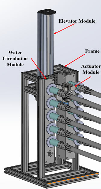
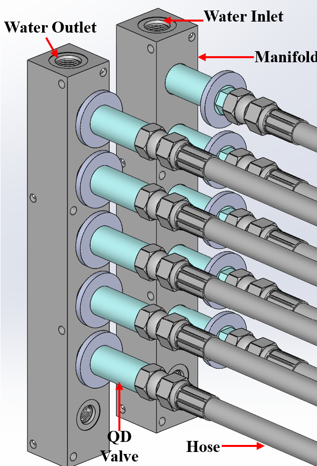
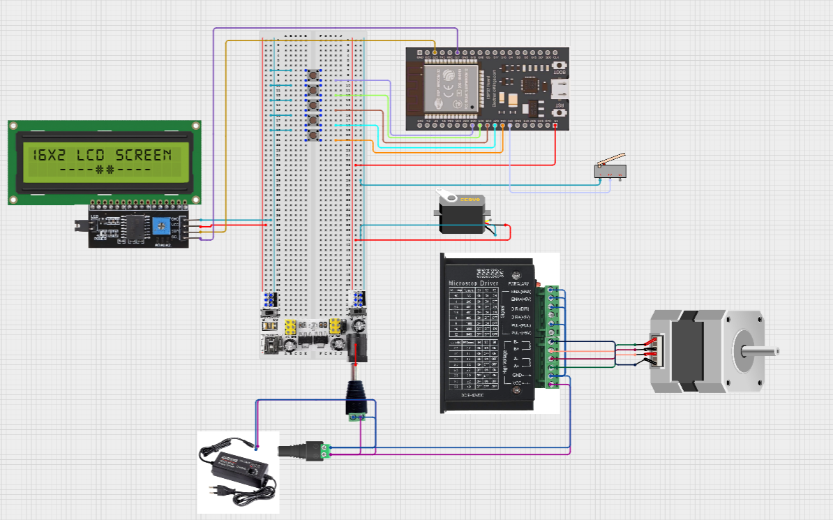
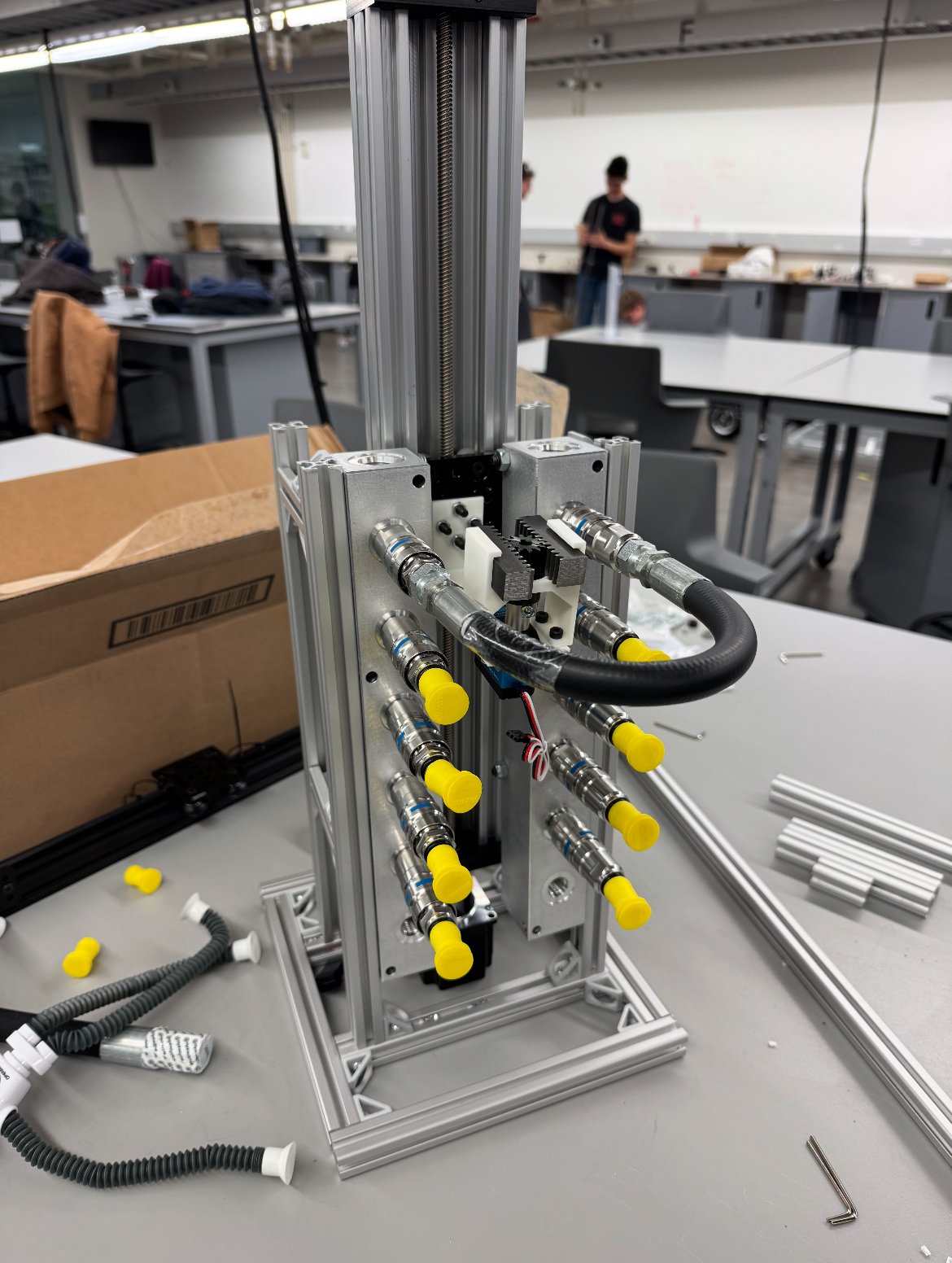
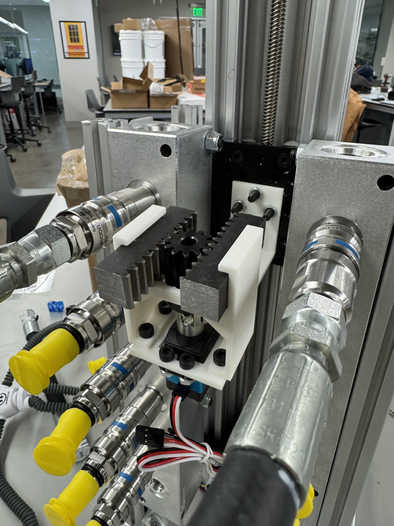
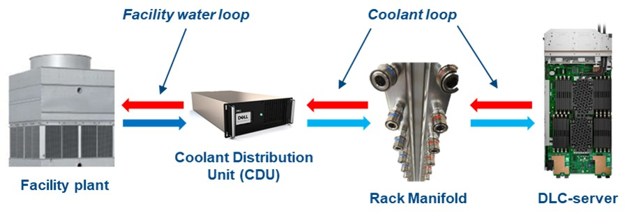
AI workloads pushed Dell’s thermal envelope past what air cooling could handle. Direct Liquid Cooling (DLC) replaced the fans with a closed loop—cold plates on every CPU and GPU, manifolds running coolant from a CDU into each rack, and a few hundred quick-disconnect (QD) fittings holding it all together.

Coolant is the new failure surface. One weeping fitting can drip onto a power supply two rack-units below and take an entire aisle offline. Dell’s existing leak-detection layer sees this fast—but the only response it has is a full-rack shutdown. A blunt tool for what is usually a node-level problem.

The cost of a single 42U rack going dark is roughly $80,000 every four hours, or about $480,000 per day—not counting the GPUs themselves, the SLA penalties, or the customer phone calls. Insurance covers the hardware. It does not cover the schedule.

FIG. 01 · DLC Loop Dell DLC system: facility plant → CDU → rack manifold → DLC server
“Design a holistic solution capable of tracking physical metrics within the liquid cooling system and preserving component health during failures.”

▪ Solution-neutral problem statement, agreed with sponsor, Sept 2024

§ 02 · The system Four modules, one job: isolate the leaking node
FIG. 02 · Labeled assembly CAD render of the assembled prototype with the four modules labeled: Elevator Module (top), Frame (8020 aluminum structure), Water Circulation Module (manifold stack on left), and Actuator Module (rack-and-pinion housing at the QDs).

The mechanism doesn't detect leaks—Dell's sensors already do that. It receives the leak-level signal, drives an actuator up the rack to that level, and physically pulls apart the two QDs feeding that server. Coolant flow to the leaking node stops. Coolant flow to every other node continues. The data center never sees an aisle drop.

  • Four modules, one job — each independently testable, each replaceable without taking the others apart.
  • Built inside an 8020 aluminum frame sized to a Dell rack column.
  • Five-level test stand, not a full 42U tower — exercises every motion the production version would.
01

Actuator

Servo-driven rack-and-pinion in a 3D-printed housing. Translates rotary motion into two opposing linear pulls, one rack each, disconnecting both supply and return QDs in a single stroke.

35 kg·cm servo · 3.4 N·m output
02

Elevator

Lead-screw vertical stage carrying the actuator. Self-locking under load, zeroes itself against a limit switch on power-on, and lands within 6 mm of the target QD center across all rack levels.

Stepper-driven · ±6 mm tolerance
03

Water circulation

Closed-loop test rig that mimics a real rack manifold. Two manifolds (intake / outlet), five levels, rigid tubing through QDs. Flow meter on the intake confirms isolation when the actuator pulls a level.

5 levels · pump · flow meter
04

Controls

ESP32 running a deterministic state machine. Limit-switch homing, preset positions per rack level, manual override, and an LCD that shows what the system is doing. No cloud round-trip—loss of network does not stop isolation.

ESP32 · stepper driver · servo PWM
§ 03 · Subsystem detail Where the design decisions actually live
FIG. 03 · Actuator subsystem CAD: rack-and-pinion actuator with 35kg servo, housing, and mounting bracket.
▪ 03.1 — ACTUATOR

One pinion, two opposing racks.

The first concept used two separate solenoids, one for each QD—two driver circuits, two timing windows, two failure modes, twice the wiring. After the first sketch I scrapped it.

  • Shipped design: single pinion driving two racks in opposite directions. One stroke disconnects both supply and return QDs simultaneously—half the parts, half the failure surface, a quarter of the wiring.
  • Force margin: required 1.25 N·m to pop a QD; specified a 35 kg·cm hobby servo (3.4 N·m output) for ~3× the load. After 50 cycles, no measurable gear wear.
  • Housing: most complex part on the build. PETG, 80% infill, 6 mm walls—up from 50% / 2 mm after the first FEA pass showed too much deflection. Strong injection-mold candidate at scale.
Drive
35 kg·cm hobby servo
Output torque
3.4 N·m
Required
1.25 N·m
Housing
PETG, 80% infill
FIG. 04 · Elevator Lead-screw elevator CAD: linear rail, screw, stepper at base, mounting plate carrying the actuator.
▪ 03.2 — ELEVATOR

Belt drive looked elegant. Lead screw won.

I trade-studied a belt-and-sprocket elevator first—faster, cheaper bearings, but it needed a brake to hold position under the actuator's reaction loads. That's another failure mode living above expensive hardware.

  • Lead screw is self-locking by geometry—cut the power, carriage stays put. Slower per turn, but cycle time is dominated by the QD pull, not the climb.
  • Net cycle time: 10.2 s, well inside the 15 s spec.
  • Limit-switch homing on every boot—without it, stepper drift compounds and the actuator starts hunting for QDs.
  • Repeatability: landed within 6 mm of every target level across 50 consecutive runs.
Drive
NEMA 17 stepper
Mechanism
Lead screw, self-locking
Repeatability
±6 mm
Homing
Limit switch, every boot
FIG. 05 · Water circulation Two manifolds, five QDs each, hoses on the right side; modeled after a real Dell rack manifold.
▪ 03.3 — WATER CIRCULATION

The shaft-collar hack that saved the project.

Stock Dell QDs are too narrow to grab with anything mechanical. Our first plan was to weld washers onto each one to give the actuator a flat face. The Fisher Engineering Design Center stopped us cold: welding heat damages the internal ball bearing that holds the QD's seal.

  • Redesigned around off-the-shelf shaft collars sized to slip over each QD body. Field-replaceable, no thermal damage, doesn't void the QD spec sheet.
  • Flagged to Dell as a future-state change: integrate the collar geometry directly into the next-gen QD body.
  • Test loop: two manifolds, five levels, rigid tubing, one pump, one shut-off valve, one bucket reservoir. Crude, but it answers the only question that matters.
  • Acceptance signal: flow meter on the intake. Pull a level's QDs, watch the rate drop. Bucket on the floor stayed empty.
Manifolds
2 (intake / outlet)
Levels
5
Loop
Closed, single pump
Telemetry
Flow meter, intake
FIG. 06 · Controls schematic ESP32 controls schematic with stepper driver, servo, LCD, push buttons, limit switch, power supply.
▪ 03.4 — CONTROLS

Deterministic. No cloud. No surprises.

The control loop is intentionally boring. ESP32, stepper driver, servo PWM line, limit switch, four buttons, 16×2 LCD, 24 V brick. On boot, it homes the elevator. On a level command, it drives to the preset, fires the servo, watches a feedback line, and reports. The state machine fits on one whiteboard.

  • No network in the loop. The brief allowed for a connected version; I argued against it. If a leak event coincides with a network blip, you do not want isolation waiting on a TCP retry.
  • Each rack runs its own loop. Dashboard integration is a wire we left for Dell to terminate on their side.
  • Manual override via push-button at the panel—operator can fire any level without the MCU.
MCU
ESP32
Power
24 V, < 2 A
Override
Manual, push-button
Network
None — local only
§ 04 · Built, not on paper The prototype, on the bench at Texas A&M

Manufacturing kept us honest. Three things we got wrong on the first pass: the cantilever beam deflected too much at the actuator end and we re-cut it from a thicker waterjet stock, the welded-collar plan died at the FEDC and turned into the shaft-collar redesign, and the business office lost a $300 purchase order for a week, which is its own kind of engineering problem.

We ran 50 consecutive dry cycles at randomized levels with no failures. We then ran the same routine with water in the loop. Flow rate measurably dropped at every disconnect; nothing leaked. The acceptance test was not subtle: a bucket on the floor stayed empty.

FIG. 07 · Assembled prototype Real photo: the assembled prototype on a lab bench, with hoses, QDs, and the elevator column visible.
FIG. 08 · Rack & pinion, in place Close-up of the steel rack and 3D-printed pinion housing installed against the manifolds.
FIG. 09 · 8020 frame, junction Photo of the 8020 aluminum frame corner, showing T-slotted gussets and assembled hardware.
§ 05 · Trade-offs worth defending What we kept, what we cut
▪ Considered

Belt-and-sprocket elevator

Faster, cheaper bearings. Needs a brake to hold position. Brake is one more thing to fail above expensive hardware.

▪ Shipped

Lead-screw elevator

Self-locking by geometry. Slower per turn, but cycle time is dominated by the QD pull, not the climb. Net response: 10.2 s.

▪ Considered

Two separate solenoids

One per QD. Two driver circuits, two timing windows, two housings, twice the wiring. Simpler to imagine, harder to build right.

▪ Shipped

Single rack-and-pinion, two opposing racks

One pinion, one motor, one stroke disconnects both QDs. Half the parts, half the failure modes.

▪ Considered

Welded washers on each QD

Gives the actuator a flat face to push against. Welding heat damages the QD’s internal ball bearing. Caught at FEDC review.

▪ Shipped

Off-the-shelf shaft collars

Field-replaceable, no thermal damage to the QD body. Flagged for Dell as a future-state QD geometry change.

▪ Considered

Network-connected control plane

Dashboard integration, telemetry, OTA updates. Couples isolation to network availability—exactly what you don’t want during a fault.

▪ Shipped

Local-only ESP32 state machine

Each rack runs its own deterministic loop. Network drop doesn’t suspend isolation. Telemetry left as an integration point for Dell.

§ 06 · Cost & production model Prototype budget, future-state BOM

What the prototype cost

Total project spend was $3,249. McMaster and Amazon carried most of the hardware; OpenBuilds supplied the elevator stage; FEDC labor covered waterjet cuts and welding. The overage on our $3,000 budget was a last-minute trip to Round Rock to deliver the prototype to Dell.

Vendor
Spend
Share
McMaster-Carr
$1,278
39%
Amazon
$824
25%
FEDC labor
$438
13%
OpenBuilds
$313
10%
Travel (Austin)
$283
9%
ServoCity, Grainger
$114
4%
Total
$3,249
100%

What it would cost at scale

If Dell were to deploy this—leveraging their supply chain—the per-unit cost for the critical hardware drops to $406.60. That excludes the controls integration into Dell’s existing rack dashboard, which is where the meaningful integration cost lives. Set against $480 K of avoided downtime per rack-day, the system pays for itself the first time it fires.

Item
Cost
Note
Elevator + lead screw + stepper
$190
OEM
Housing (injection-mold ready)
$65
at scale
Cantilever beam (waterjet)
$55
Servo motor
$29
Pinion + rack + shaft + coupler
$39
Limit switch + fasteners + step driver
$29
Per unit
$406.60
+ controls
§ 07 · Standards & manufacturability What this would take to ship through Dell’s supply chain

Design for manufacturing

The two-rack / one-pinion consolidation already pulled significant part count out of the design. The cantilever beam is one waterjet cut and a single bend, with welds we could eliminate at thicker stock. The 3D-printed housing is the bottleneck: it’s the most geometrically complex part and it’s the right candidate for an injection mold once volume justifies the tooling.

The lead-screw elevator came from OpenBuilds as an off-the-shelf assembly. Cheap and reliable, but it has a lot of small parts and resists automation. A future redesign would consolidate the carriage into a single machined plate with captive bearings.

Design for assembly

Standardized fasteners across the build (M4 / M5 throughout). Most interfaces are obvious; the rack mounts to a cabinet with four bolts. Two known assembly pain points flagged for the next revision: the cantilever-to-elevator joint is fiddly, and the servo mount needs an asymmetric keying feature so it can’t be installed backwards.

▪ Standards referenced

In the drawings, in the FMEA, in the future-state BOM.

ASME Y14.5 (2018)GD&T — positional and parallelism tolerances on the actuator interfaces.
SAE J1739 (2021)FMEA framework for the risk study (RPN scoring, mitigation actions).
ISO 4162 (2012)Metric fastener tolerances—single sourcing across the build.
ASME B18.3 (2012)Socket-head cap screws used at every fine-assembly interface.
ASME B1.20.1 / B31.3Reserved for a future fluid-handling integration spec.
ASME P30.1 (2024)Load-handling guidance for installation in a rack cabinet.
ASHRAE 90.4 (2022)Energy efficiency considerations for the data-center context.
IEC 60529 — IP53Target enclosure rating for the housing and electronics.
§ 08 · Broader impact Where this goes after the capstone

The handoff

After the Engineering Project Showcase, we drove the prototype to Dell’s Round Rock headquarters and walked through every subsystem with their thermal-systems and patent teams. The prototype is now Dell property; what they do with it next is their call.

Where else this lives

The core idea—vertical-travel actuator that disconnects fluid lines on demand—isn’t specific to data centers. The patent embodiments cover that surface area deliberately.

  • HVAC plant rooms — chiller-line maintenance without dropping the loop.
  • Automotive assembly lines — coolant and fuel-line stations.
  • Aerospace fuel-line testing — leak isolation under bench conditions.
  • Medical fluidics — dialysis and other patient-loop equipment.

What it changes for the operator

It removes the human from the critical 4-hour window. A leak no longer means “page someone, drive in, find the right rack, find the right level, kill the loop manually.” The system isolates the node, surfaces the affected level, and waits for an acknowledgment. The technician still fixes the QD—they just don’t have to race the dripping coolant to do it.

▪ IP STATUS

Patent pending.

Dell’s legal team identified the node-level isolation solution as IP worth protecting. We submitted documentation, met with their patent counsel, and the application is filed.

The patent covers the combination of a vertical-travel module and a QD actuation module, with multiple embodiments for each.

▪ Embodiments covered
  • VerticalLead screw, belt drive, scissor lift
  • ActuationRack & pinion, linear solenoid, cam & follower
  • TriggerExternal leak signal from existing detection layer
§ 09 · Close What I led, what the team did

Five mechanical engineering seniors. I was the primary designer and team lead. I owned the mechanical concept end-to-end: the rack-and-pinion actuator, the housing geometry, the cantilever-beam interface, the FEA validation, and the integration of the four modules into a single frame.

I also took on the project-management surface: sponsor cadence with Dell’s thermal team, the IP submission process, the Gantt chart, and the schedule recovery when the business office lost a purchase order. Danny, Juan, Wilson, and Noah built the elevator integration, the controls, the water loop, and the validation harness, respectively. The prototype is theirs as much as it is mine.

Acknowledgements. Eric Tunks and Ben Sy at Dell, who treated us like junior engineers, not students. Dr. Jacob McFarland and Dr. Dorrin Jarrahbashi at Texas A&M for the technical critique. The Fisher Engineering Design Center for the waterjet time and for stopping us from welding through a $40 part.